Gas Sampling Pump Features
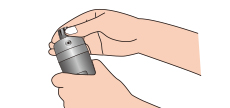
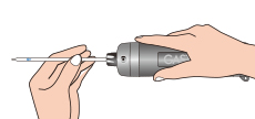
The built-in tip breaker incorporates a diamond edge for maximum
durability that cuts the surface of the detector tube. This makes the
tip breaking much easier, safer and convenient. Discarded tips are
deposited in a storage bin for safe and easy disposal.
The pump piston has been designed with a smaller diametre so that the
handle can be pulled out with even less effort. This permits anyone to
operate the pump easily. Also, GASTEC Pump Model GV-110 and GV-100 meet
the leakage test of EN1231, Workplace atmospheres-Short term detector
tube measurement systems-Requirements and test methods, 4.2 Detector
tube pump, 4.2.2 Leakage "The detector tube pump with the closed
detector tube connection shall be tight, so that during the first minute
of a pump stroke the leakage rate does not exceed 3mL/min." The GASTEC
pump shaft shows you the leakage rates with a red line.
The pump body is covered with a soft elastomer, with the middle portion
narrower than the ends to ensure a firm grip on the pump cylinder. The
other outer surfaces of the pump are made of non sparking materials of
ABS resin except for the opening of the tube tip cutter, which is made
of chromed stainless steel.
The full-stroke (100mL) and the half-stroke (50mL) positions are marked
exactly by the red line on the pump shaft, and the handle is precisely
locked at those positions. The attached flow finish indicator tells you
automatically when the stroke is complete. When the white disk pops
out,the sample is complete.
The automatic stroke counter built in model GV-110 (in Model GV-110S)
gas sampling pump can track up to ten pump strokes automatically so
there is no chance of miscounting.
Operating procedures (Simple 3-step measuring)
|
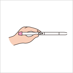
- 1.
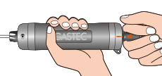
- Break off both ends of the detector tube. Insert the tube into the rubber inlet.
|
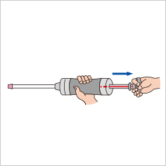
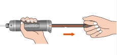
- 2.
- Pull out the handle until it is locked. Wait until the sampling time has elapsed.
|
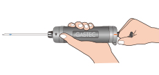
- 3.
- Wait for the required sampling time and read the measurement at the end of the coloured layer.
|
Airtightness test
If the sampling pump is not airtight, measurements will not yield
correct results. Before starting to measure, be sure to verify that the
sampling pump is really airtight.
- 1.
- First, confirm that the inlet nut is not loose.
|
- 2.
- Insert a detector tube (with both tips intact) into the rubber tube inlet of the sampling pump.
|
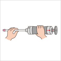
- 3.
- With the handle fully pushed in, align both of
the guide marks (red line + triangle) on the pump (tail-end block) and
the handle (▲100).
|
- 4.
- Pull out the handle in one thrust until it is
locked, and then release the handle. Wait until the sampling time
(approx. 1 minute) has elapsed.
|
- 5.
-
Grasp the handle and turn it 90
degrees. If the pump is completely airtight, the handle should readily
return to its original position; with the handle's demarcation read line
fully concealed.
Note)
When you
return the piston, please ease it back gradually (lightly holding on to
it so it does not snap back in one thrust. (Since there is a vacuum
inside the cylinder, the handle tends to return rapidly). If it snaps
back too hard, the impact can damage the pump causing it to malfunction.
|
|
When the airtightness test does not provide the desired result
Primary causes of leakage in gas sampling pumps are looseness of the
inlet nut, porosity of the inlet rubber, impure or insufficient sealing
grease, etc. Please perform the necessary maintenance according to the
procedures described in the sampling pump instructions manual. If the
pump still leaks after performing the maintenance procedures according
to the manual, immediately discontinue use, and contact your authorized
GASTEC representative.
|


 gas sampling pump can track up to ten pump strokes automatically so there is no chance of miscounting.")